شعار

المدونة

وطن

المدونة

  • ما هي مضخة الطرد المركزي؟ أجزاؤها، مبدأ عملها، وأنواعها ما هي مضخة الطرد المركزي؟ أجزاؤها، مبدأ عملها، وأنواعها
    Aug 04, 2025
    مقدمةالمضخة الطاردة المركزية هي جهاز ميكانيكي يقوم بتحويل الطاقة الدورانية للمكره إلى طاقة حركية للسوائل لنقل السوائل. مضخات الطرد المركزي تُستخدم على نطاق واسع في صناعات مثل معالجة المياه، والنفط والغاز، والمعالجة الكيميائية، وأنظمة التدفئة والتهوية وتكييف الهواء، وهي معدات أساسية لنقل السوائل بكفاءة. في هذه المقالة، سنستكشف مبدأ عمل مضخات الطرد المركزي، ومكوناتها الرئيسية، وأنواعها المختلفة، وتطبيقاتها لمساعدتك على فهم شامل لمضخات الطرد المركزي. تابع القراءة لمعرفة المزيد!كيف تعمل مضخة الطرد المركزي؟ يعتمد مبدأ عمل مضخة الطرد المركزي على محرك كهربائي يدفع المكره للدوران بسرعة عالية، مما يُسبب تدفقًا دوارًا للسائل داخل المضخة، ويولّد طاقة حركية عالية عند مخرج المكره. تحت تأثير قوة الطرد المركزي، يتدفق السائل على طول غلاف المضخة نحو المخرج أو يُنقل إلى المكره التالي. في الوقت نفسه، تتشكل منطقة ضغط منخفض في مركز المكره نتيجة تدفق السائل، مما يُحدث فرقًا في الضغط مع السائل عند مدخل الشفط، مما يدفع السائل إلى دخول جسم المضخة باستمرار. مع استمرار دوران المكره، تُحقق المضخة عملية شفط وتفريغ مستمرة، مُكملةً بذلك عملية نقل السائل. قطع غيار مضخات الطرد المركزيال أجزاء مضخة الطرد المركزي تتكون بشكل رئيسي من المكره، وأغلفة المضخات، وأعمدة المضخات، ومجموعات المحامل، وأجهزة الختم، ومنافذ السحب والتفريغ، ومحركات الدفع. فيما يلي الخصائص الوظيفية لكل مكون: المكره: المكره هو العنصر الدوار الذي يمنح الطاقة الحركية للسائل، مما يولد قوة الطرد المركزي لتحريك السائل إلى الخارج.غلاف المضخة: يحيط الغلاف بالمكره ويوجه تدفق السائل من المكره إلى مخرج التفريغ أثناء تحويل السرعة إلى ضغط.العمود: ينقل العمود الطاقة الميكانيكية من المحرك إلى الدافع، مما يحافظ على الدوران والمحاذاة المستقرة.مجموعة المحمل: تدعم المحامل العمود وتقلل الاحتكاك، مما يجعل التشغيل سلسًا ودقيقًا.الختم الميكانيكي أو التعبئة: يمنع السائل من التسرب على طول العمود حيث يخرج من الغلاف.فوهات الشفط والتفريغ: تسمح فوهة الشفط للسائل بالدخول إلى المضخة، بينما تقوم فوهة التفريغ بتوجيهه للخارج تحت الضغط.المحرك أو السائق: يوفر المحرك الطاقة اللازمة لتدوير الدافع ودفع عملية الضخ. أنواع المضخات الطاردة المركزيةتتوفر مضخات الطرد المركزي الصناعية بتصاميم ونماذج متنوعة لتلبية احتياجات التطبيقات الصناعية المختلفة. فيما يلي بعض الأنواع الشائعة:مضخة الطرد المركزيمضخة مغناطيسيةمضخة ذاتية التحضيرمضخة غاطسة مضخات الدفع المغناطيسي: تستخدم تقنية الدفع المغناطيسي الخالية من التسرب، وهي مناسبة لنقل الوسائط القابلة للاشتعال أو المتفجرة أو السامة (مثل المذيبات والكلور السائل).المضخات شبه الغاطسة: يكون المحرك مكشوفًا فوق سطح السائل، ومناسبًا للتطبيقات ذات التقلبات الكبيرة في مستوى المياه (مثل محطات الصرف، والتحكم المؤقت في الفيضانات).مضخات التحضير الذاتي: مزودة بوظيفة تحرير الهواء، مما يلغي الحاجة إلى التحضير اليدوي، ومناسبة للشفط المتقطع (على سبيل المثال، موازنة السفن، تصريف موقع البناء).مضخات الحجاب الحاجز: تستخدم الحركة الترددية للحجاب الحاجز لنقل السوائل عالية اللزوجة أو التي تحتوي على جسيمات (على سبيل المثال، الملاط، الطلاء).مضخات المياه: تصميم عام لنقل المياه النظيفة (على سبيل المثال، إمدادات المياه البلدية، والري الزراعي).مضخات الحمض:مصنوعة باستخدام مواد مقاومة للتآكل (على سبيل المثال، PVDF، Hastelloy)، ومصممة خصيصًا للوسائط الحمضية (على سبيل المثال، حمض الكبريتيك، وحمض الهيدروكلوريك).مضخات القلوية:مجهزة بأختام خاصة وتقنيات معالجة المواد، ومناسبة للسوائل القلوية القوية (على سبيل المثال، هيدروكسيد الصوديوم، والإلكتروليت). ما هي استخدامات مضخة الطرد المركزي؟ تُستخدم المضخات الطاردة المركزية الصناعية على نطاق واسع في العديد من الصناعات:المياه ومياه الصرف الصحي: نقل المياه النظيفة ومياه الصرف الصحي ومياه الأمطار إلى محطات المعالجة.النفط والغاز: نقل النفط الخام وسوائل التكرير ومياه البحر في العمليات البحرية.الكيمياء والصيدلة: التعامل مع الأحماض المسببة للتآكل والمذيبات والسوائل الصيدلانية المعقمة.محطات الطاقة: مياه التغذية المتداولة للغلايات، ومياه التبريد، والمكثفات في توليد الطاقة.التعدين والتصنيع: ضخ المواد الكاشطة والمبردات الصناعية.الزراعة: توزيع مياه الري والمواد الكيماوية الزراعية بكفاءة.مزايا المضخات الطاردة المركزية كفاءة عالية: تم تصميمها لتحويل الطاقة بشكل مثالي، وتوفير معدلات تدفق فائقة مع الحد الأدنى من استهلاك الطاقة.صيانة منخفضة: التصميم الميكانيكي المبسط مع مكون دوار واحد فقط (المكره) يقلل من التآكل والصيانة.مساحة صغيرة: تتكيف التكوينات الرأسية/الأفقية الموفرة للمساحة مع التصميمات الصناعية المحدودة.تنوع المواد: متوفر في الفولاذ المقاوم للصدأ والحديد الزهر والبلاستيك الفلوري والبوليمرات المتقدمة للتعامل مع الوسائط المسببة للتآكل/الكاشطة.تشغيل بدون نبضات: تضمن الحركة الدورانية المستمرة نقل السوائل بسلاسة وبدون اهتزازات وهو أمر بالغ الأهمية للعمليات الدقيقة. خاتمةتتميز مضخات الطرد المركزي بتعدد استخداماتها وكفاءتها العالية واستخدامها الواسع، مما يجعلها من المعدات الأساسية لأنظمة توصيل السوائل الحديثة. وبصفتنا مزودًا متخصصًا لحلول المضخات، نركز على تلبية احتياجات مناولة السوائل الخاصة بمختلف الصناعات، ونقدم خدمات شاملة ومخصصة. إذا كنتم بحاجة إلى حل الضخ الأنسب لظروف عملكم، فلا تترددوا في التواصل مع خبرائنا الفنيين للاستشارات.
    إقرأ المزيد
  • فهم أجزاء مضخة الطرد المركزي وطريقة عملها فهم أجزاء مضخة الطرد المركزي وطريقة عملها
    Aug 21, 2025
    مضخة الطرد المركزي هي نوع من المضخات يستخدم مبدأ قوة الطرد المركزي لنقل السوائل. وظيفتها الأساسية هي تحويل الطاقة الحركية الدورانية للمحرك الكهربائي إلى طاقة سائلة، مما يُولّد تدفقًا وضغطًا. في هذه المقالة، سنتناول بالتفصيل المكونات الرئيسية لمضخة الطرد المركزي ومبادئ عملها. سنُفصّل كل مكون ونشرح آلية عمله لمساعدتك على فهم هذه المعدات بشكل واضح وشامل.     أجزاء مضخة الطرد المركزي على الرغم من وجود العديد أنواع المضخات الطاردة المركزية مع اختلاف تطبيقاتها، تتشابه هياكلها الأساسية. سيساعدك فهم هذه المكونات الرئيسية على فهم آلية عمل مضخات الطرد المركزي. سنقدم مقدمة مفصلة عن المكونات الأساسية الرئيسية لمضخات الطرد المركزي، بما في ذلك المراوح، وأغلفة المضخات، وأنظمة الختم. المكره إنه أحد المكونات الأساسية للمضخة الطاردة المركزية، وهو المسؤول في المقام الأول عن نقل الطاقة الميكانيكية من المحرك إلى السائل، وتوليد قوة الطرد المركزي لنقل الطاقة الحركية والطاقة الكامنة إلى السائل. أنواع المكرهات: بناءً على شكلها الهيكلي، تُصنف إلى أنواع مفتوحة، وشبه مفتوحة، ومغلقة. تتميز المراوح المغلقة بأعلى كفاءة وهي الأكثر استخدامًا، بينما تُناسب المراوح المفتوحة وشبه المفتوحة نقل السوائل التي تحتوي على جسيمات صلبة أو لزجة. عند تشغيل مضخة الطرد المركزي، يدفع عمود المضخة المكره للدوران بسرعة عالية، مما يُجبر السائل المملوء مسبقًا بين الشفرات على الدوران. وتحت تأثير قوة الطرد المركزي بالقصور الذاتي، يتحرك السائل شعاعيًا من مركز المكره إلى محيطه الخارجي. يكتسب السائل طاقةً أثناء تدفقه عبر الدافع. عندما يغادر السائل الدافع ويدخل غلاف المضخة، يتباطأ بسبب توسع قنوات التدفق تدريجيًا داخل الغلاف، محولًا جزءًا من طاقته الحركية إلى طاقة ضغط ساكنة، ثم يتدفق بشكل عرضي إلى أنبوب التفريغ.   غلاف المضخة: يُشير غلاف المضخة إلى قناة تدفق حلزونية الشكل، ذات مساحة مقطعية متزايدة تدريجيًا، تمتد من مخرج الدافع إلى مدخل دافع المرحلة التالية أو إلى أنبوب مخرج المضخة. تتسع قناة التدفق تدريجيًا، محولةً الطاقة الحركية للسائل إلى طاقة ضغط ساكنة، تُصرف بعد ذلك عبر الأنبوب. الوظائف الرئيسية: جمع السوائل عالية السرعة المتدفقة من مخرج الدافع؛ تحويل الطاقة الحركية للسائل إلى طاقة ضغط بشكل فعال؛ توجيه السائل المضغوط بسلاسة إلى أنابيب تفريغ المضخة؛ تحمل ضغط السائل داخل المضخة.   الأنواع: غلاف المضخة على شكل صدفة الحلزون: هو النوع الأكثر شيوعًا، وله مقطع عرضي لقناة التدفق على شكل حلزوني وبنية بسيطة. غلاف مضخة ريشة التوجيه: يتميز بريش توجيه ثابت مُركّب حول محيط الدافع. تُحوّل ريش التوجيه الطاقة الحركية للسائل إلى طاقة ضغط، وتُوجّه السائل نحو المخرج. يُستخدم عادةً في المضخات متعددة المراحل أو مضخات الضغط العالي.   عمود المضخة وظيفتها الأساسية هي نقل الطاقة ودعم المكره للحفاظ على التشغيل الطبيعي في وضع التشغيل. ولأنها تؤدي وظائف إضافية لتحويل الطاقة، يجب أن تتمتع مادتها بالقوة والصلابة ومقاومة التآكل الكافية. وعادةً ما تُصنع من فولاذ سبائك عالي القوة. يتم توصيل المكره والعمود بمفتاح. ولأن هذه الطريقة لا تُمكّن إلا من نقل عزم الدوران، ولا تُثبّت الموضع المحوري للمكره، يُستخدم غلاف عمود وصامولة قفل في المضخة لتثبيت المكره.   كم العمود يحمي غلاف العمود عمود المضخة، ويحوّل الاحتكاك بين الحشوة والعمود إلى احتكاك بينهما. ولذلك، يُعدّ غلاف العمود من المكونات المعرضة للتآكل في مضخات الطرد المركزي. يمكن عادةً معالجة سطح غلاف العمود بطرق مثل الكربنة، والنيترة، والطلاء بالكروم، أو الطلاء. يجب أن تتراوح خشونة السطح عادةً بين Ra3.2 وRa0.8 ميكرومتر. هذا يُقلل معامل الاحتكاك ويطيل عمر الخدمة.   ختم زيت الهيكل العظمي يُعدّ مانع تسرب الزيت الهيكلي أحد أكثر أنواع مانعات التسرب شيوعًا واستخدامًا في أعمدة الدوران، ويُعرف عادةً باسم مانعات تسرب الزيت. وتتمثل وظيفته الأساسية في سد زيت التشحيم (أو الشحم) داخل المعدات الميكانيكية، مع منع دخول الملوثات الخارجية، مثل الغبار والطين، إلى النظام. مبدأ عمل مضخة الطرد المركزي يعتمد مبدأ عمل مضخة الطرد المركزي على دوران المكره بسرعة عالية، مما يُنقل الطاقة الحركية إلى السائل تحت تأثير قوة الطرد المركزي، ويحوّلها إلى طاقة ضغط، مما يُحقق نقل السوائل. قبل بدء التشغيل، يجب ملء غلاف المضخة وأنابيب الشفط بالكامل بالوسط لمنع التجويف. أثناء التشغيل، يُحرّك المكره الدوار السائل بسرعة عالية ويُقذف نحو الحافة الخارجية، بينما تتشكل منطقة ضغط منخفض في مركز المكره، مما يسحب السائل باستمرار وينقله إلى المخرج. ومن خلال التشغيل الدوري المستمر، تتحقق عملية نقل ثابتة ومتواصلة.     خاتمة من خلال المحتوى أعلاه، نعتقد أنكم أصبحتم الآن على دراية جيدة بأجزاء مضخة الطرد المركزي وكيفية عملها. إذا كانت لديكم أي أسئلة أو مشاكل فنية أخرى بخصوص هذه المعدات، فلا تترددوا في التواصل مع الفريق الفني لشركة تشانغيو في أي وقت. سنرد عليكم بسرعة خلال ٢٤ ساعة ونعالج استفساراتكم.
    إقرأ المزيد
  • What Is The Difference Between Magnetic Drive Pump Vs Centrifugal Pump What Is The Difference Between Magnetic Drive Pump Vs Centrifugal Pump
    Sep 05, 2025
    Both magnetic drive pumps and centrifugal pumps belong to the category of centrifugal pumps, widely used in industrial fluid transfer applications. They both utilize centrifugal force to increase fluid kinetic energy and pressure, yet they exhibit numerous differences. This article provides an in-depth analysis of the differences between magnetic drive pumps vs centrifugal pumps. We'll comprehensively compare their working principles, structure, application areas, advantages, and disadvantages. This will help you clearly understand how to make the most informed choice based on your medium characteristics, safety requirements, and budget. Please continue reading to find the pumping solution best suited to your project needs. I. Working Principle Magnetic Drive Pump: Magnetic drive pumps utilize magnetic coupling principles to transmit power. When the motor operates, it drives the outer magnetic rotor to rotate at high speed. Through the magnetic field interaction, the inner magnetic rotor within the isolation sleeve rotates synchronously, thereby driving the impeller to perform centrifugal motion. Its enclosed transmission structure fundamentally eliminates leakage risks. Although magnetic drive pumps employ a different transmission method, they still belong to the category of centrifugal pumps, all relying on the centrifugal force generated by impeller rotation to convey fluids.   Centrifugal Pump: As the most prevalent fluid transfer equipment, centrifugal pumps operate based on the centrifugal effect generated by impeller rotation. When the motor drives the pump shaft to rotate the impeller at high speed, the fluid is flung from the impeller's center toward its periphery under centrifugal force. During this process, the fluid's kinetic and pressure energy continuously increase, ultimately forming a stable flow stream discharged through the outlet. This highly efficient energy conversion method makes it the most widely used pump type in industrial applications.   II. Structure Magnetic drive pump: Magnetic pump mainly consists of two parts: the driving part (including the motor and the external magnet) and the transmission part (including the internal magnet and the impeller). The power transmission is achieved through magnetic coupling between the two parts, without the need for a traditional shaft seal structure, good sealing and leak-free.   Centrifugal pump: Centrifugal pumps are usually composed of impellers, pump bodies, pump shafts, bearings, sealing rings and other parts. Among them, as an important component to block fluid leakage, the seal may fail due to wear or media corrosion during long-term operation, causing leakage problems.   III. Applications Magnetic Drive Pumps: Featuring a shaftless design that completely eliminates leakage risks, magnetic drive pumps offer excellent corrosion resistance. They are particularly suitable for conveying flammable, explosive, toxic, or highly corrosive media. These pumps are widely used in high-risk and high-purity processes such as petroleum refining, fine chemicals, biopharmaceuticals, surface treatment, and environmental engineering.   Centrifugal Pumps: Centrifugal pumps feature robust mechanical construction, stable operational performance, and excellent adaptability to varying conditions, making them one of the most widely used fluid transfer devices. They are extensively applied in industrial processes, agricultural irrigation, municipal water supply and drainage, building fire protection, and HVAC systems.  
    إقرأ المزيد
  • Horizontal vs Vertical Centrifugal Pumps and How to Choose Horizontal vs Vertical Centrifugal Pumps and How to Choose
    Sep 01, 2025
    In industrial fluid transfer systems, horizontal centrifugal pumps and vertical centrifugal pumps are the two most common pump types. Simply put, horizontal centrifugal pumps feature a horizontally mounted shaft, a simple structure, and are widely used in water supply, air conditioning circulation, and industrial pressurization applications. Vertical centrifugal pumps, with their vertically oriented shafts, are commonly used for pumping from low-level liquid reservoirs (such as underground tanks or drainage pits) or in applications with limited installation space. Although both belong to the centrifugal pump category and share similar hydraulic performance, they exhibit significant differences in structure, installation, maintenance, and application scenarios. Below, we provide a detailed comparison across multiple dimensions to help you make a more suitable choice.   Structural Comparison Horizontal centrifugal pumps feature a horizontally arranged shaft, with the motor typically directly coupled to the pump body via a coupling. This compact design facilitates installation and commissioning. Visually, their base is usually monolithic and requires anchoring to a foundation platform.   Vertical centrifugal pumps employ a vertical shaft design, with the motor positioned above the pump body, allowing the pump to operate submerged in liquid. Their slender structure generally eliminates the need for additional foundation supports, allowing direct installation atop tanks or reservoirs to save floor space.   Working Principle Despite differing installation methods, both share identical core operating principles. Both horizontal and vertical centrifugal pumps rely on the centrifugal force generated by a high-speed rotating impeller to expel fluid, creating a vacuum that draws in liquid for continuous conveyance.   Advantages and Application Scenarios Comparison   Horizontal Centrifugal Pump Advantages and Applications   Advantages:   Easy Maintenance: Simple structure requires no pipeline disassembly or motor lifting during repairs, facilitating inspection and component replacement. Stable Operation: Typically suited for steady-state conditions. Installation must ensure level positioning, resulting in low vibration and reliable operation. Applications: Horizontal centrifugal pumps are the preferred choice for most conventional applications, commonly used in factory water supply, cooling systems, industrial cleaning, and similar scenarios.   Advantages and Applications of Vertical Centrifugal Pumps   Advantages:   Suitable for Backflow Conditions: Particularly effective for suctioning media from underground tanks or low-level liquid reservoirs, addressing the insufficient suction lift limitations of many horizontal pumps (non-self-priming types). Space-Saving: Vertical design minimizes footprint and eliminates the need for specialized foundations, making it ideal for installations with limited space. No Self-Priming Issues: Effectively handles low-level suction demands that horizontal pumps struggle to manage.   Applications: Vertical pumps are primarily used for lifting and conveying liquids from lower elevations, such as deep well water extraction, tunnel drainage, sewage treatment, and medium transfer within chemical containers.   How to Choose Between Horizontal and Vertical Centrifugal Pumps?   The selection between horizontal and vertical pumps primarily depends on actual operational requirements:   Installation Conditions: If ample space is available for foundation construction, prioritize the easier-to-maintain horizontal pump. For confined spaces or direct tank mounting, select a vertical pump.   Liquid Level Position: For pumping from underground tanks or low-level media, choose a vertical centrifugal pump. Standard horizontal centrifugal pumps have poor self-priming capability and cannot meet such requirements.   Maintenance Costs Horizontal pumps feature simpler maintenance with lower associated costs. Vertical pumps, however, require more complex servicing—including full lifting for repairs—and necessitate regular inspection and replacement of their submerged sliding bearings. Failure to do so may increase shaft runout, leading to mechanical failures. Installation demands absolute vertical alignment and high precision.   In Summary In summary, horizontal and vertical centrifugal pumps are complementary products designed for distinct application scenarios. Horizontal pumps excel in simplicity and ease of maintenance, making them ideal for most standard applications. Vertical pumps, however, are unmatched in low-level pumping and space-saving designs, proving indispensable in specific operating conditions.   Should you encounter any technical issues regarding pump selection, application, or maintenance, please feel free to contact our professional technical team at any time. We will provide detailed explanations and reliable solutions.
    إقرأ المزيد
  • Six Types of Acid Resistant Pumps and Selection Guide Six Types of Acid Resistant Pumps and Selection Guide
    Sep 04, 2025
    Acid-resistant pumps are widely used in chemical production processes, typically for conveying acidic and alkaline liquids, with acidic liquids being the predominant type. Due to the highly corrosive nature of acidic media, many conventional acid-resistant pump materials are unsuitable for handling such liquids. Selecting the appropriate acid-resistant pump requires a comprehensive evaluation based on specific operating conditions, such as concentration, temperature, and pressure. Below, we introduce six types of acid-resistant pumps and their selection methods. Please continue reading this article.   1. Hydrochloric Acid Pump In chemical production, the concentration of commonly used industrial hydrochloric acid is generally 38%, making it highly corrosive. Therefore, pumps conveying hydrochloric acid require flow-through components made of corrosion-resistant plastic. Considering equipment lifespan, operational stability, and overall cost-effectiveness, we recommend FZB fluoroalloy centrifugal pumps or CYQ magnetic drive pumps. These pump types not only excel in material corrosion resistance but also offer significant advantages in operational efficiency, maintenance costs, and reliability, better meeting the economic and long-term requirements of hydrochloric acid conveying applications.   2. Sulfuric Acid Pump The selection of pumps for conveying sulfuric acid depends on its concentration. Pumps are primarily classified into two categories: dilute sulfuric acid pumps and concentrated sulfuric acid pumps. For dilute sulfuric acid, a wider range of materials are available, including engineering plastics, ceramics, F46 (fluoroethylene propylene), or F26 (fluororubber). Concentrated sulfuric acid, on the other hand, is highly corrosive and oxidizing, and fluoroplastics (such as CYF Series Fluoroplastic Centrifugal Pump) are generally required. Due to the high density of concentrated sulfuric acid, special attention should be paid to the power rating when selecting a pump motor. It is recommended to multiply the shaft power by 1.84 to avoid motor overload.   3. Hydrofluoric Acid Pump Hydrofluoric acid (HF) is extremely corrosive and can severely attack most metals and ceramics. Therefore, when transporting HF, it is strongly recommended to use a fluoroplastic magnetic drive pump to ensure equipment safety and durability. It is particularly important to replace all ceramic components within the pump with HF-resistant materials (such as polytetrafluoroethylene (PTFE), modified polypropylene, or carbon graphite) to prevent corrosion, leakage, and equipment failure.   4. Nitric Acid Pump When transporting nitric acid, it is recommended to use a highly corrosion-resistant fluoroplastic magnetic drive pump. Furthermore, the rubber seals within the pump body should be replaced with polytetrafluoroethylene (PTFE) to enhance sealing safety and service life.   5. Acetic Acid Pump   Acetic acid is a highly corrosive organic acid that is corrosive to many metals. Ordinary carbon steel will corrode severely in acetic acid at all concentrations and temperatures and is therefore unsuitable for use in this medium. Stainless steel, particularly molybdenum-containing 316 stainless steel, has excellent acetic acid resistance and can be used in high-temperature and dilute acetic acid vapor environments. For demanding applications involving high temperatures, high concentrations of acetic acid, or other corrosive media, high-alloy stainless steel or fluoroplastic magnetic drive pumps (such as the CQB magnetic drive pump) are recommended.   6. Brine (Seawater) Pumps   In chloride ion environments such as sodium chloride solutions, seawater, and brackish water, the uniform corrosion rate of ordinary steel is relatively low, but coatings are still generally required for protection. Various types of stainless steel also exhibit low overall corrosion rates in such media, but are susceptible to localized corrosion (such as pitting and crevice corrosion) caused by chloride ions. Although 316 stainless steel offers excellent resistance to chloride ion corrosion, it is relatively expensive. Considering both cost and reliability, fluoroplastic centrifugal pumps (such as IHF chemical centrifugal pumps) are recommended. These materials effectively resist chloride ion corrosion, offer a long service life, and offer a low overall cost.   Conclusion   In summary, the selection of industrial acid-resistant pumps requires comprehensive consideration of the media composition, concentration, temperature, and specific operating conditions. The correct choice of pump material and structural type is directly related to the safety, stability, and service life of the production system. When operating in complex conditions such as highly corrosive media, high temperatures, high concentrations, or the presence of solid particles, professional selection experience and technical judgment are essential.   If you have any questions regarding pump selection or actual application, please feel free to contact our technical team. We can provide you with targeted selection suggestions and professional technical support.  
    إقرأ المزيد
  • Types of Centrifugal Pumps and How to Select Types of Centrifugal Pumps and How to Select
    Aug 30, 2025
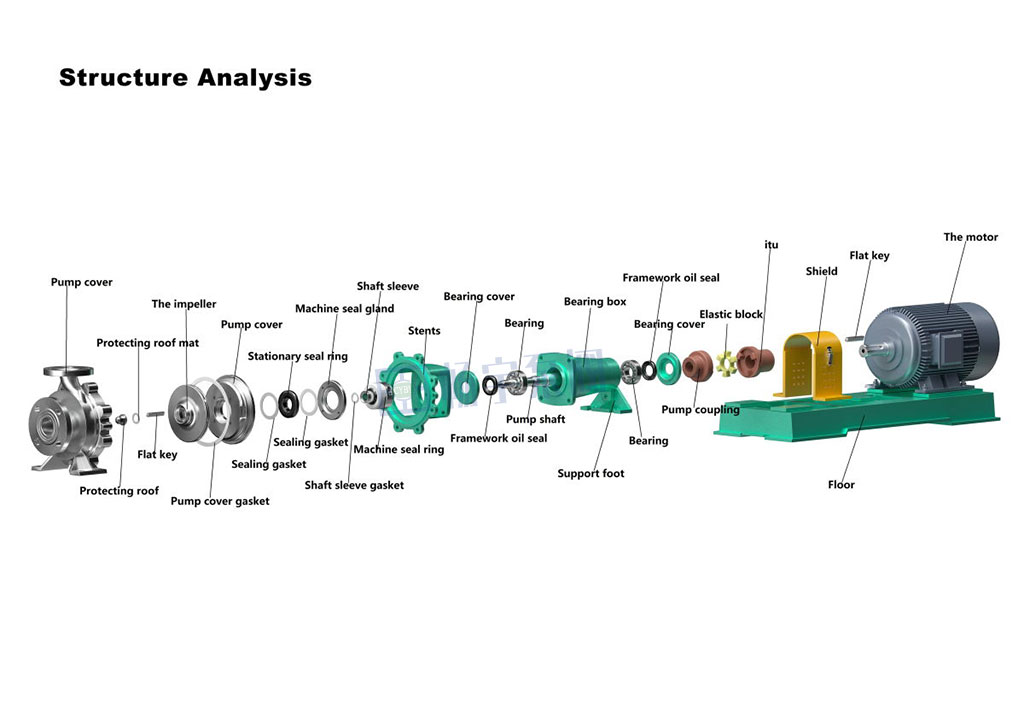
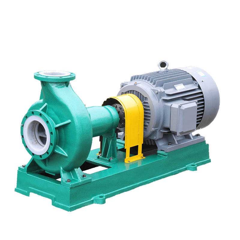
    Centrifugal pumps are fluid transfer equipment widely used in industrial, agricultural, and municipal applications. Their primary function is to generate centrifugal force through a rotating impeller, transferring liquids from low-pressure areas to high-pressure zones to achieve lifting, circulation, or pressurization. So, what types of centrifugal pumps exist? What are the characteristics and suitable scenarios for different structures? This article provides a detailed analysis of the seven primary classification methods for centrifugal pumps, helping you gain a comprehensive understanding of their types and key selection criteria. I. Classification by Working Pressure Based on operating pressure, centrifugal pumps are categorized into low-pressure, medium-pressure, and high-pressure pumps.   Low-pressure pumps are suitable for scenarios requiring pressures below 100 meters water column (mwc), such as general water supply systems. Medium-pressure pumps operate at pressures between 100 and 650 mwc and are commonly used in industrial processes. High-pressure pumps handle pressures exceeding 650 mwc, making them ideal for high-pressure spraying, boiler feedwater, and similar applications.   II. Classification by Number of Impellers Based on the number of impellers, pumps can be categorized as single-stage or multi-stage. Single-stage pumps feature a single impeller, offering simple structure and easy maintenance; Multi-stage pumps mount multiple impellers on a single shaft, with total head being the sum of individual stage heads. They are suitable for high-head applications like high-rise water supply or mine drainage.   III. Classification by Impeller Inlet Configuration Pumps are categorized as single-suction or double-suction based on inlet arrangement. Single-suction pumps feature impellers with inlet on one side only, offering compact design; Double-suction pumps have impellers with inlet on both sides, delivering higher flow rates and smoother operation. They are suitable for high-volume applications like municipal water supply or large-scale irrigation.   IV. Classification by Pump Shaft Orientation Pumps are classified as horizontal or vertical based on shaft orientation. 
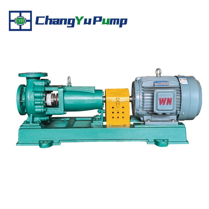
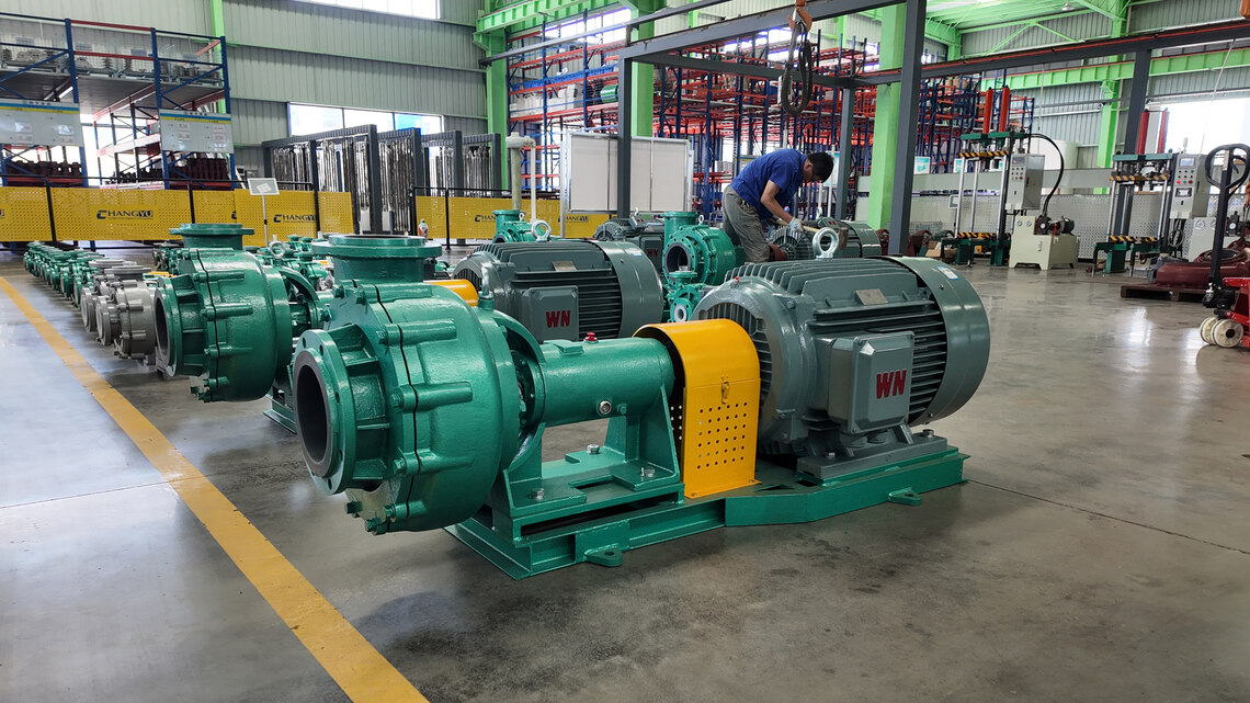
Horizontal centrifugal pumps feature a horizontally positioned shaft, facilitating installation and maintenance but occupying more space; 
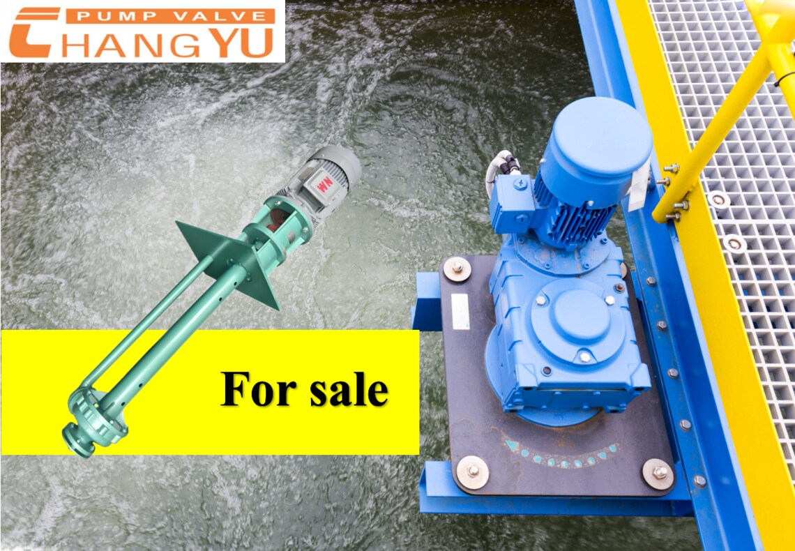
Vertical centrifugal pumps have a vertically arranged shaft, requiring minimal floor space and being suitable for confined areas like well pumping or ship bilge drainage.   V. Classification by Pump Housing Joint Type Based on housing structure, pumps are categorized as horizontally split or vertically split. Horizontal split casings divide along the axial centerline for easy internal component access; Vertical split casings separate vertically, suitable for high-pressure applications with superior sealing integrity.   VI. Classification by Flow Guidance Method Based on how flow exits the impeller, pumps are categorized as volute pumps or guide vane pumps. Volute pumps collect and discharge liquid through a spiral-shaped casing, offering simple structure and high efficiency; Guided-flow pumps direct water flow to the next stage or outlet via guide vanes, commonly used in multistage pumps or high-precision flow control applications.   VII. Classification by Conveyed Medium Centrifugal pumps are categorized by medium type into clean water pumps, oil pumps, corrosion-resistant pumps, etc. Clean water pumps handle uncontaminated liquid media; Oil pumps specialize in oil-based media with robust sealing and temperature resistance; Corrosion-resistant pumps utilize stainless steel, plastic, or similar materials for acids, alkalis, and other corrosive liquids.   How to Select the Right Centrifugal Pump for Your Needs? After understanding the various types of centrifugal pumps, the most critical step is selecting the correct model based on actual operating conditions and application requirements. Improper selection may lead to inefficiency, increased energy consumption, or even equipment damage. Below are several core selection factors:   Determine medium characteristics (select by conveyed medium): This is the primary step in selection. The properties of the conveyed liquid must be clearly defined, such as:   Water or similar liquids: Standard water pumps may be selected. Oils, fuels, etc.: Select specialized oil pumps with seals and materials suitable for flammable/explosive media. Acids, alkalis, salts, and other corrosive liquids: Must use corrosion-resistant pumps (e.g., stainless steel, fluoroplastic materials).   Additionally, consider the medium's viscosity, solid content, temperature, etc.   
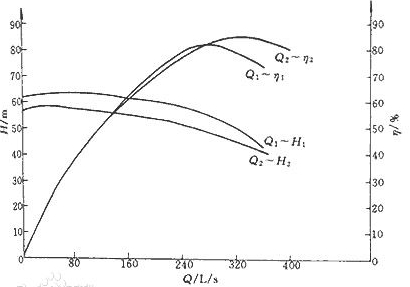
Confirm Flow Rate and Head Requirements (Based on Pressure and Impeller Count):   Flow rate (Q): Volume of liquid to be transported per unit time (m³/h or L/s). Head (H): Total pressure head the pump must overcome (meters).   Based on calculated required pressure and flow rate, the pump category can be preliminarily determined:   High head, low flow: Multistage pumps may be selected. High flow, medium-low head: Double-suction pumps may be selected. Low-pressure, low-flow applications: Single-stage, single-suction pumps may be more economical.   Consider installation environment and space (based on pump shaft orientation):   Horizontal pumps: Facilitate installation and maintenance but occupy larger floor space, suitable for pump rooms with ample room. Vertical pumps: Require minimal floor space, ideal for confined areas (e.g., deep wells, pits, vessels).   Reference operating conditions and reliability (select by structural type):   For applications requiring frequent maintenance, horizontal split-case pumps allow access without disassembling piping, offering exceptional convenience. When demanding exceptional operational stability and minimal vibration (e.g., large-scale water supply systems), double-suction pumps are the preferred choice due to their symmetrical inlet design and balanced axial forces.   Selection Process Summary: First analyze the medium characteristics, then calculate the required flow rate and head. Next, consider installation space, budget constraints, and future maintenance convenience. Finally, comprehensively reference the above classification features to determine the most suitable centrifugal pump type.   Conclusion In summary, centrifugal pumps offer diverse types, each with unique structural features and application scenarios. Proper selection not only impacts system efficiency but directly influences equipment lifespan and operational costs. Should you have any questions regarding centrifugal pump selection, application, or technical details, feel free to consult our professional technical team for free. We provide personalized answers and tailored solutions!
    إقرأ المزيد
  • How to Calculate Centrifugal Pump Efficiency How to Calculate Centrifugal Pump Efficiency
    Aug 31, 2025
    In industrial and civil applications, centrifugal pumps are widely used in water treatment, heating and cooling, irrigation, drainage, and other scenarios. Understanding a centrifugal pump's efficiency not only helps evaluate its operational status but also guides energy conservation, reduces maintenance costs, extends equipment lifespan, and prevents excessive wear. Today, we'll explain how to calculate centrifugal pump efficiency—covering principles, calculation methods, and practical significance.    I. What Is Pump Efficiency?   Pump efficiency fundamentally measures a machine's ability to convert input energy into useful output energy. If 1 unit of input energy yields only 0.5 units of output, the efficiency is 50%. While seemingly straightforward, real-world engineering involves diverse energy forms and units—mechanical, electrical, hydraulic, etc. Appropriate conversion factors enable unit comparison and standardized efficiency calculations. II. Calculating Centrifugal Pump Efficiency 1. Definition of Overall Efficiency For centrifugal pumps (using water as the medium), overall efficiency is defined as the ratio of output power to input shaft power:   Ef = Pw / Ps   Where:   Ef —— Overall efficiency; Pw —— Output power (hydraulic water power); Ps —— Input shaft power (brake horsepower, BHP).   2. Water Power Conversion (US Units)   Under commonly used US units, the water power formula is:   Pw = (Q × H) / 3960   Q: Flow rate (GPM, gallons per minute) H: Head (ft)   3960: Constant for converting GPM × ft to horsepower (BHP)   Example: For a pump operating at 30 ft head and 100 GPM flow rate, if BHP = 1, then:   Pw = (100 × 30) / 3960 ≈ 0.757 BHP, yielding an efficiency of approximately 75.7%.   3. Three Components of Overall Efficiency   The overall efficiency of a centrifugal pump is actually the product of three component efficiencies:   Mechanical efficiency (ηₘ): Friction losses from bearings, stuffing boxes, or mechanical seals. Volumetric efficiency (ηᵥ): Leakage losses due to wear rings, balance holes, and blade clearances. Hydraulic efficiency (ηₕ): Energy losses caused by friction within the impeller and pump casing.   Therefore:   η_total = ηₘ × ηᵥ × ηₕ   Among these factors, hydraulic efficiency is often the most significant contributor to centrifugal pump efficiency.   III. Why Significant Efficiency Variations? Underlying Design Principles   During the design phase, the primary adjustable parameters for centrifugal pumps are the impeller and volute (or diffuser, guide vanes), analogous to the rotor and stator in electric motors. The relationship between impeller parameters and rotational speed/diameter is fundamental:   Head is proportional to the square of rotational speed: Doubling speed quadruples head; minor diameter adjustments follow similar patterns. Flow rate is proportional to speed or diameter: doubling either parameter doubles the flow rate.   Additionally, the impeller's cross-sectional area, flow channel width and depth, inlet dimensions, and blade shape directly impact fluid flow efficiency, thereby influencing overall performance. Historically, pump design relied heavily on manual trials and iterative prototype testing. Today, engineers can leverage empirical formulas and parameters like specific speed to rapidly identify optimal design starting points.   IV. how to Calculate Centrifugal Pump Efficiency​ in Practice?   Actual Flow Rate Q: Obtain true GPM using a flow meter; Measure Head H: Derive from pressure differential conversion, units in ft; Record Shaft Power Ps: Obtain BHP (or kW) using power measurement equipment; Calculate water power Pw: Input Q and H from above; Derive efficiency: Ef = Pw ÷ Ps;   Further analyze efficiency components: If efficiency is low, use thermal imaging, leak testing, vibration analysis, etc., to identify which component is causing the efficiency drop (mechanical, volumetric, hydraulic). Conclusion   Centrifugal pump efficiency serves as a critical metric for evaluating operational performance, energy conservation levels, and operating costs. Overall efficiency comprises three components: hydraulic, mechanical, and volumetric losses. Understanding the design principles of impellers and volutes—such as the specific speed curve—provides a solid foundation for both design and diagnostic processes. By measuring actual flow rate, head, and shaft power, formulas like Pw = (Q × H) / 3960 can quantify pump efficiency. If efficiency is low, identify and improve corresponding components to enhance overall performance.   Should you encounter any questions during pump selection, efficiency measurement, optimization, or diagnostics, our expert team stands ready to assist. With extensive experience and specialized equipment, we are committed to delivering efficient, safe, and reliable pump solutions.
    إقرأ المزيد
  • How Does a Horizontal Centrifugal Pump Work How Does a Horizontal Centrifugal Pump Work
    Sep 02, 2025
    In industrial production, horizontal centrifugal pumps are used for liquid transfer. They serve as core equipment in water supply systems, HVAC, industrial cooling, fire protection systems, chemical processes, irrigation, and wastewater treatment. Typically requiring continuous operation and consuming significant power, the rational and economical selection and use of horizontal centrifugal pumps are crucial for ensuring efficient and stable system operation while reducing energy consumption and maintenance costs. This article will provide a detailed analysis of the basic structure and working principle of horizontal centrifugal pumps, helping you gain a deeper understanding and utilization of them. What is a horizontal centrifugal pump? A horizontal centrifugal pump is a fluid transfer device widely used in industrial applications, characterized by its horizontally arranged pump shaft. It converts mechanical energy into fluid kinetic and pressure energy through centrifugal force, enabling liquid lifting, pressurization, and transportation. Due to its compact structure, smooth operation, easy maintenance, and high efficiency, the horizontal centrifugal pump has become an indispensable key piece of equipment in modern industrial production. Horizontal Centrifugal Pump Parts A horizontal centrifugal pump primarily consists of the following core components:   Impeller: The pump's core working component. Typically equipped with 4 to 12 backward-curved blades fixed to the pump shaft, it rotates at high speed driven by an electric motor. Its function is to directly transfer mechanical energy to the liquid, serving as the pump's energy supply unit. The shape, dimensions, and material of the impeller directly impact the pump's performance and efficiency.   Pump Casing: Usually designed as a volute casing, it surrounds the impeller externally. It serves two primary functions: collecting the liquid ejected at high speed from the impeller and, through its uniquely designed gradually expanding flow cross-section, efficiently converting the liquid's kinetic energy into static pressure energy. The casing features a suction inlet at its central top, connecting to the suction piping, and a discharge outlet on its side, connecting to the discharge piping.   Pump Shaft: Transfers power, connecting the motor to the impeller to enable high-speed rotation.   Mechanical Seal / Packing: Located where the shaft exits the casing, preventing high-pressure fluid leakage while blocking air ingress to ensure efficient operation.   Bearing: Supports the pump shaft, reduces rotational friction resistance, and bears radial and axial loads to ensure smooth pump operation.   Suction and Discharge Piping: The suction line typically incorporates a non-return foot valve at its end to ensure the pump and suction pipe are filled with liquid before startup, preventing air lock. The discharge line is equipped with a control valve to regulate flow rate and pressure.   Working Principle of Horizontal Centrifugal Pumps Horizontal centrifugal pumps operate by imparting centrifugal motion to liquid through a high-speed rotating impeller, converting mechanical energy into kinetic and pressure energy. After gaining energy within the impeller, the liquid flows into the volute-shaped pump casing where its velocity decreases. Part of the kinetic energy is further converted into static pressure energy, ultimately forming a stable high-pressure output. Simultaneously, a low-pressure zone forms at the impeller inlet, drawing in liquid continuously through pressure differential to achieve uninterrupted medium conveyance.     In Summary Horizontal centrifugal pumps feature relatively simple structures and operating principles, making them widely applicable in industrial fluid conveyance. A thorough understanding of its structural components and operational principles is fundamental for proper equipment selection, achieving efficient and economical operation, and timely troubleshooting. If you require a horizontal centrifugal pump tailored to specific operating conditions, or have any questions regarding pump technology, selection, or maintenance, our professional technical team stands ready to assist. Contact our technical team today for expert solutions and consultation services.
    إقرأ المزيد
  • Sewage Pumps vs Clean Water Pumps: Definition, Selection, and Differences Sewage Pumps vs Clean Water Pumps: Definition, Selection, and Differences
    Sep 03, 2025
    In the industrial and municipal sectors, pumps are essential components of fluid transport systems. Common pump types include sewage pumps and clean water pumps, which differ significantly in their structural design, application scenarios, and operating principles. Understanding the characteristics and usage of these two types of pumps will help companies make informed decisions regarding engineering design, equipment selection, and maintenance management.   This article will explain the definitions of sewage pumps and clean water pumps, how to choose the right pump, and the key differences in their structure and performance.   What is a sewage pump?   ChangYu Sewage pump is a drum pump, with a motor integrated into the pump. Compared to traditional horizontal or vertical sewage pumps, sewage pumps are compact and require less space. They are typically used to transport sewage containing solid particles or fibrous materials, industrial wastewater, and domestic wastewater. They are widely used in municipal wastewater treatment, industrial drainage, and low-lift drainage systems.     To prevent clogging, sewage pumps feature a large flow path design that allows for smooth passage of impurities and particles in the wastewater. However, due to this, their efficiency is slightly lower than that of clean water pumps, and their lift is generally not high.   What is a clean water pump?   Clean water pumps are primarily used to transport clean water or liquids with physical and chemical properties similar to clean water. They are widely used in industrial and municipal water supply and drainage, high-rise building pressure boosting, garden sprinkler irrigation, firefighting pressure boosting, long-distance transportation, HVAC/refrigeration cycles, farmland irrigation, and hot and cold water circulation systems.   Clean water pumps are designed with smaller flow paths and tighter clearances, which allows them to achieve higher lift under the same conditions, making them suitable for high-pressure and long-distance transportation of clean water.   How to choose between a sewage pump and a clean water pump?   When selecting a pump, consider the liquid properties, conveying distance, required head, and on-site operating conditions:   Sewage pumps are suitable for:   Sewage, wastewater, industrial liquids containing solids Low-head drainage, basement drainage, sewage treatment plants   Clean water pumps are suitable for:   Clean water or similar liquids High-rise building water supply and boosting, fire protection systems, garden sprinkler irrigation, and hot and cold water circulation   Note: Due to the compact design of the flow path and impeller, clean water pumps are not suitable for sewage or liquids containing solids. If used for sewage, they are prone to clogging, entanglement, wear, or corrosion, resulting in damage or even failure of the pump.   This comparison shows that pump selection must be based on the liquid properties and operating environment. Failure to do so can lead to equipment damage, inefficiency, and even safety accidents.   Conclusion   In summary, sewage pumps and clean water pumps each have their advantages. The former is suitable for conveying sewage containing solids and industrial wastewater, while the latter is suitable for conveying and boosting clear water or similar liquids. In industrial, construction, and municipal engineering, choosing the right pump type is key to ensuring efficient and stable system operation. If you have any questions about sewage or clean water pump selection, application, or maintenance, or have specific purchasing needs, please feel free to contact our professional team for customized solutions and quotes.
    إقرأ المزيد
  • How Does a Centrifugal Pump Operate: Safety Operation Guide How Does a Centrifugal Pump Operate: Safety Operation Guide
    Aug 30, 2025
    Centrifugal pumps are among the most common fluid transfer devices in industrial production. They operate by generating centrifugal force through impeller rotation, accelerating fluid and conveying it to the target location. Due to their simple structure, stable flow rate, and easy maintenance, they are widely used in chemical, water treatment, energy, pharmaceutical, and other industries. However, improper operation not only shortens equipment lifespan but may also cause safety incidents. Therefore, mastering standardized operating procedures is crucial for ensuring stable production while safeguarding personnel and equipment. The following systematically outlines key operational points for starting, running, and stopping centrifugal pumps to help achieve safe and efficient operation. I. Pre-Operation Preparations Before starting the centrifugal pump, conduct a systematic inspection to ensure the equipment is in a safe condition:   Document and Record Review: Verify maintenance records are complete and data accurate. Prepare operational log forms. Environmental Cleanup: Clear debris from the pump body and surrounding area to ensure a tidy operating zone. Structural Integrity Check: Verify foundation bolts are tightened, motor grounding is secure, and inlet piping, auxiliary components, and instruments are intact. Coupling and Rotation Direction Verification: Inspect coupling connection status. Before coupling, confirm motor rotation direction aligns with the pump body's directional arrow. Lubrication System Inspection: Ensure adequate lubricant level in the sump (oil level approximately 2mm below the centerline of the dipstick), with qualified oil quality and level within the 1/2 to 2/3 range. Cooling and Sealing System: Verify cooling water flow is unobstructed and seal oil pressure exceeds pump inlet pressure by 0.05–0.15MPa. Hand Turning Test: Manual rotation should exhibit no binding or abnormal noise. Temperature Preconditioning: Preheat high-temperature pumps; pre-cool low-temperature pumps. Priming and Venting: For suction-side operation, prime the pump or evacuate air; for back-priming operation, fill with liquid and vent air, then close the discharge valve. Electrical Inspection: Contact an electrician to perform motor insulation testing before energizing. II. Startup Procedure Close the discharge valve during centrifugal pump startup to reduce startup load and protect the motor:   Close inlet/outlet pressure gauge valves, outlet valve, and bypass pipe valve. Start the motor (may jog first to confirm correct rotation). Gradually open the outlet valve while simultaneously monitoring current and pressure values to ensure they do not exceed rated limits. Check for leakage from mechanical seals or packing seals; mechanical seal leakage should be less than 10 drops per minute (for light oil). Verify normal operation of the cooling and lubrication systems.   III. Operational Monitoring and Maintenance During normal pump operation, continuously monitor the following:   Bearing and motor temperatures: Bearing temperature rise must not exceed 75°C. Forced lubrication system oil temperature should remain below 28°C. Flow regulation: Never adjust flow using the inlet valve to prevent cavitation. Install a bypass pipe for prolonged low-flow operation. Abnormal noise monitoring: Immediately investigate or shut down upon detecting unusual sounds. Vibration and Seal Condition: Regularly record vibration readings and verify seal leakage remains within permissible limits. Periodic Lubricant Replacement: Lubricant replacement is recommended every 1500 operating hours.   IV. Shutdown Procedure Proper shutdown prevents water hammer, freezing, and equipment damage. Follow these steps:   Slowly close the discharge valve (close the suction valve in backflow conditions). Disconnect the motor power supply. Close valves in the external priming seal system. In low-temperature environments, drain all liquid from the pump to prevent freezing. For long-term shutdown, clean the pump, apply rust prevention, seal the inlet and outlet ports, and conduct regular inspections and maintenance.   In summary Proper operation and maintenance of centrifugal pumps are crucial for ensuring long-term stable performance and extending service life. Every step—from comprehensive pre-startup inspections to continuous monitoring during operation and standardized shutdown procedures—is vital. Adhering to the above steps not only enhances production efficiency but also minimizes the risk of malfunctions and safety incidents.   Should you encounter any operational issues or require further technical support, please contact our professional technical team at any time. We will provide timely and reliable solutions.
    إقرأ المزيد
  • مضخة الطرد المركزي المبطنة بالفلور والبولي إيثيلين ذات الوزن الجزيئي العالي للغاية: الحل الهندسي الأمثل لنقل كلورات الصوديوم مضخة الطرد المركزي المبطنة بالفلور والبولي إيثيلين ذات الوزن الجزيئي العالي للغاية: الحل الهندسي الأمثل لنقل كلورات الصوديوم
    Jul 16, 2025
    خاصية الأكسدة القوية (ORP)>+1000 ملي فولت) وميل التبلور لمحلول كلورات الصوديوم يجعله "قاتلًا للضخ"، في حين أن مضخة مبطنة بالفلور وقد حققت المواد المركبة المقواة باستخدام البولي إيثيلين عالي الوزن الجزيئي (UHMWPE) تحسناً مذهلاً في الأداء من خلال ابتكار المواد المركبة. ① قفزة في الأداء جلبتها المواد المركبة 1. ثورة مقاومة التآكل 1.1 إضافة UHMWPE (الوزن الجزيئي ≥3 مليون) يزيد من مقاومة التآكل بمقدار 8 مرات (اختبار ASTM D4060) 1.2 قدرة حافة المكره على مقاومة تآكل الجسيمات هي 3.2 مرة من قدرة حافة المكره العادية مضخة F46 (القياس الفعلي في ظل ظروف تركيز 15٪ يحتوي على ملاط بلوري) 2. مقاومة التآزر بين درجة الحرارة والتآكلنطاق درجة الحرارةأداء F46 النقيأداء UHMWPE المعززأقل من 80 درجة مئويةالتآكل السنوي: 0.008 مم0.005 ملم80-120 درجة مئويةعرضة للتشقق الإجهاديالحفاظ على هيكل الشبكة الكاملالتعرض قصير المدى حتى 150 درجة مئويةتشوه لا رجعة فيهيمكنه تحمل 4 ساعات من الصدمة الحرارية ② مقارنة المعلمات الهندسية الرئيسية 1. دورة الحياة: 1.1 وقت التشغيل المستمر: 8000 ساعة للمضخة المبطنة بالفلور العادية مقابل 25000 ساعة للمضخة المبطنة بالفلور ذات الجزيئات العالية جدًا 1.2 تم تمديد فترة الإصلاح إلى 5 سنوات (في ظل ظروف تبلور كلورات الصوديوم) 2. أداء كفاءة الطاقة: 2.1 الكفاءة الحجمية > 92%2.2 توفير 15-18% من الكهرباء مقارنة بالمضخات المبطنة بالفلور العادية ③ التحقق الاقتصادي من التكلفة الكاملة 1. الاستثمار الأولي: أقل بنسبة 40% من مضخات Hastelloy وأعلى بنسبة 25% من المضخات المبطنة بالفلور العادية 2. المزايا الشاملة: 2.1 انخفاض استهلاك قطع الغيار بنسبة 60% 2.2 انخفاض خسائر التوقف المفاجئ بنسبة 92% دراسة حالة: بعد أن استخدمت شركة في جيانغشي هذا النوع من المضخات لنقل كلورات الصوديوم، انخفضت تكلفة الصيانة السنوية لخط واحد من 280 ألفًا إلى 65 ألفًا، وزادت الطاقة الإنتاجية بنسبة 23%. (الكتاب الأزرق لجمعية صناعة الكلور والقلويات الصينية 2025). يمكن الاطلاع على هذه الحالة.
    إقرأ المزيد
  • تحليل أسباب الاهتزازات غير الطبيعية للمضخات الغاطسة والتدابير المضادة لها تحليل أسباب الاهتزازات غير الطبيعية للمضخات الغاطسة والتدابير المضادة لها
    Jul 08, 2025
    أولا: تشخيص السبب الجذري للاهتزاز 1.1 الاهتزاز الميكانيكي (يمثل 45٪ من أسباب الفشل)· فشل التوازن الديناميكي للمكره (>0.5 مم/كجم يحتاج إلى تصحيح)· تجاوز خلوص المحمل المعياري (الخلوص الشعاعي)>0.15 مم)· انحراف مركز الاقتران (خطأ الزاوية ≥ 0.05 مم/م) 1.2 اهتزازات السوائل الديناميكية (تمثل 35% من أسباب الفشل)· ظاهرة التجويف (NPSHa<NPSHr+0.5 م)· إثارة التيار الدوامي (ارتفاع المخاطر عند معدل التدفق)>2.5 متر/ثانية)· محتوى الغاز المتوسط ​​يتجاوز المعيار (>نسبة الحجم 5٪) 1.3 الرنين الهيكلي (يمثل 20٪ من أسباب الفشل)· يتطابق التردد الطبيعي مع تردد السرعة (±10% منطقة الخطر)· مسافة دعم خط الأنابيب كبيرة جدًا (أنابيب الفولاذ الكربوني>3م بدون دعم) ثانياً: عملية التحقيق في الموقع1. اكتشاف قيمة الاهتزاز: إذا >4.5 مم/ثانية، ثم (تحليل الطيف)2. تحديد ما إذا كان الاهتزاز عالي التردد؟3. إذا كانت الإجابة بنعم: تحقق من المحامل/التروسإذا لم يكن كذلك: تحقق ما إذا كان هذا اهتزازًا منخفض التردد؟4. إذا كان الاهتزاز منخفض التردد: تحقق من المكره/الوصلةإذا لم يكن اهتزازًا منخفض التردد: تحقق من نظام السوائل ثالثا. الحلول3.1 التعديل الميكانيكيموازنة ديناميكية للمروحة G6.3 (اختلال التوازن المتبقي
    إقرأ المزيد
1 2 3 4 5 6 7

اترك رسالة

اترك رسالة
إذا كنت مهتمًا بمنتجاتنا وتريد معرفة المزيد من التفاصيل، فيرجى ترك رسالة هنا، وسنقوم بالرد عليك في أقرب وقت ممكن.
إرسال

ساعات العمل لدينا

الإثنين 21/11 - الأربعاء 23/11: 9 صباحًا - 8 مساءً
الخميس 24/11: مغلق - عيد شكر سعيد!
الجمعة 25/11: 8 صباحًا - 10 مساءً
السبت 26/11 - الأحد 27/11: 10 صباحًا - 9 مساءً
(جميع الساعات بالتوقيت الشرقي)

اتصل بنا :jade@changyupump.com

وطن

منتجات

whatsApp

الاتصال